Bellows Replacement
 With
the engine now firmly attached to the boat, I returned to
the business of replacing the flexible bellows on my outdrive. There are
actually three bellowses back there: One contains the drive shaft and universal
joints that connect the drive unit to the engine, another carries engine exhaust
out through the outdrive, and a wee little one goes on the cable that operates
the forward/reverse gear shifting mechanism.
With
the engine now firmly attached to the boat, I returned to
the business of replacing the flexible bellows on my outdrive. There are
actually three bellowses back there: One contains the drive shaft and universal
joints that connect the drive unit to the engine, another carries engine exhaust
out through the outdrive, and a wee little one goes on the cable that operates
the forward/reverse gear shifting mechanism.
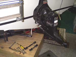
 The
first step was to remove the drive. Since I planned to rebuild my water pump, I
went ahead and took the lower unit off first, then disconnected the trim
cylinders and removed the six nuts that hold the upper unit to the bell housing.
The drive shaft was stuck in the gimbal bearing, so it took some not-so-gentle
persuasion to get the drive loose. Tilting the upper drive unit up and then
carefully slamming it down against the stop finally broke it free. (You may be
wondering how you slam carefully: it mostly involves applying a little more
force with each blow and hoping that it comes loose before something breaks.)
The
first step was to remove the drive. Since I planned to rebuild my water pump, I
went ahead and took the lower unit off first, then disconnected the trim
cylinders and removed the six nuts that hold the upper unit to the bell housing.
The drive shaft was stuck in the gimbal bearing, so it took some not-so-gentle
persuasion to get the drive loose. Tilting the upper drive unit up and then
carefully slamming it down against the stop finally broke it free. (You may be
wondering how you slam carefully: it mostly involves applying a little more
force with each blow and hoping that it comes loose before something breaks.)
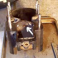
 Next,
the bell housing was removed. Under the trim position sender and limit switch on
either side of the bell housing, there's a pair of hinge pins that are threaded
into the housing. I purchased the special tool that's required to remove them
along with all the other stuff for this job. The bellows themselves are held on
with large hose clamps similar to the ones on an automobile radiator hose.
Next,
the bell housing was removed. Under the trim position sender and limit switch on
either side of the bell housing, there's a pair of hinge pins that are threaded
into the housing. I purchased the special tool that's required to remove them
along with all the other stuff for this job. The bellows themselves are held on
with large hose clamps similar to the ones on an automobile radiator hose.
With
the hinge pins out, I moved the housing back far enough to loosen the clamps and
loosen one end of each bellows. There's a sequence to it that allows you to get
to the clamps: The big u-joint bellows is separated at the gimbal housing end.
The exhaust bellows stays attached to the gimbal plate and is separated at the
bell housing end. The sliding gadget on the end of the shift cable has to be
removed and the inner cable pulled out to allow the bell housing to come free.
There's also a 5/8" water hose that goes from the back of the bell housing
to a pipe in the gimbal housing. Removing the water pipe isn't too difficult,
but according to one
Internet source, putting it back on is "where most people give
up."
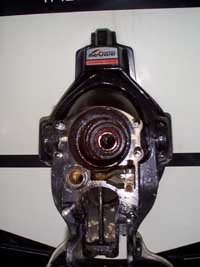
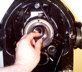
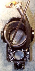
 After
getting the bell housing out of the way and removing the remaining parts of the
shift cable, I took a closer look at my gimbal bearing. The drive shaft passes
through and is supported by this bearing. Mine had a decidedly unfavorable rough
feel to it when turned by hand. I decided I'd have to replace it. I had hoped I
wouldn't have to replace the bearing because the procedure in the Mercruiser
manual for removing it sounded like quite a chore. You need a slide hammer
or a very expensive special
tool to remove it according to the manual.
After
getting the bell housing out of the way and removing the remaining parts of the
shift cable, I took a closer look at my gimbal bearing. The drive shaft passes
through and is supported by this bearing. Mine had a decidedly unfavorable rough
feel to it when turned by hand. I decided I'd have to replace it. I had hoped I
wouldn't have to replace the bearing because the procedure in the Mercruiser
manual for removing it sounded like quite a chore. You need a slide hammer
or a very expensive special
tool to remove it according to the manual.
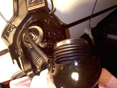
 Fortunately,
before I went to all that trouble I found a how-to
article at mercstuff.com that described a much simpler method. According to
the article, prior to 1983 Mercruiser installed the ring that houses the bearing
with the cutouts facing the rear, so that you could remove the bearing without
removing the ring. Sure enough, the cutouts were there on my 1977 bearing and I
was able to rotate the old bearing and remove it without much trouble at all.
Fortunately,
before I went to all that trouble I found a how-to
article at mercstuff.com that described a much simpler method. According to
the article, prior to 1983 Mercruiser installed the ring that houses the bearing
with the cutouts facing the rear, so that you could remove the bearing without
removing the ring. Sure enough, the cutouts were there on my 1977 bearing and I
was able to rotate the old bearing and remove it without much trouble at all.
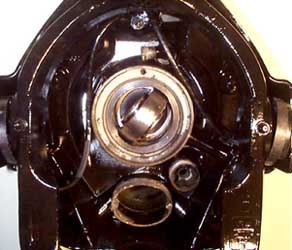
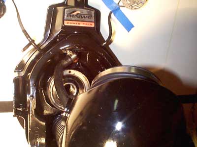
 Putting
the new one in is the reverse of the removal procedure. I put the new bearing in
through the cutouts, being careful to make sure the grease holes in the outer
race would end up toward the front of the boat. Then I rotated the bearing into
position and viola, nothing
to it and no special tools required.
Putting
the new one in is the reverse of the removal procedure. I put the new bearing in
through the cutouts, being careful to make sure the grease holes in the outer
race would end up toward the front of the boat. Then I rotated the bearing into
position and viola, nothing
to it and no special tools required.
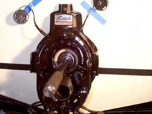
 Next
I aligned the engine to the drive. The engine's front mount is adjustable and
allows the engine to be tilted along it's fore and aft axis to line it up with
the drive shaft. An alignment
tool is required for this step. The alignment tool goes for about $70 and is
essentially a big metal stick that simulates the drive shaft. You adjust the
engine position until the tool slides easily through the bearing and into the
splined drive coupler on the back of the engine. I continued adjusting and
removing and inserting the tool until the grease marks on the tool showed up
evenly all the way around when I pulled it out.
Next
I aligned the engine to the drive. The engine's front mount is adjustable and
allows the engine to be tilted along it's fore and aft axis to line it up with
the drive shaft. An alignment
tool is required for this step. The alignment tool goes for about $70 and is
essentially a big metal stick that simulates the drive shaft. You adjust the
engine position until the tool slides easily through the bearing and into the
splined drive coupler on the back of the engine. I continued adjusting and
removing and inserting the tool until the grease marks on the tool showed up
evenly all the way around when I pulled it out.
 I found the seal for the upper shift shaft to be a little worse for wear, so I
replaced that while I was in there. I cleaned all the corrosion off the aluminum
parts and gave everything a nice shiny coat of Mercruiser Phantom Black, too.
I found the seal for the upper shift shaft to be a little worse for wear, so I
replaced that while I was in there. I cleaned all the corrosion off the aluminum
parts and gave everything a nice shiny coat of Mercruiser Phantom Black, too.
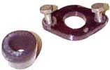
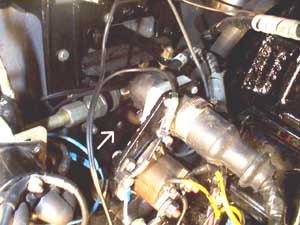 I
found another procedure
at mercstuff.com that looked like it would make replacing that 5/8" water
hose a whole lot easier. The hose attaches to a little pipe that goes through
the gimbal ring and connects to another hose that goes up to the front of the
engine. There are two screws and a metal piece that hold the pipe in its rubber
bushing. (The pipe bushing looks suspiciously like one of the trim cylinder
attaching bushings, by the way.)
I
found another procedure
at mercstuff.com that looked like it would make replacing that 5/8" water
hose a whole lot easier. The hose attaches to a little pipe that goes through
the gimbal ring and connects to another hose that goes up to the front of the
engine. There are two screws and a metal piece that hold the pipe in its rubber
bushing. (The pipe bushing looks suspiciously like one of the trim cylinder
attaching bushings, by the way.)
It
took some effort to get the pipe out there, but having it out let me put the
pipe on the end of the hose while the bell housing was off the boat and
everything was easy to get to.
I purchased a new trim position sender and trim limit switch
set along with everything else, so I yanked the old ones out and replaced them at this point. If you've been
following this story from the beginning, you may recall that early on I had to
replace the wiring for the trim sender and switch and I did it with the drive in
place. Let me just say it's a whole heck of a lot easier to replace those pieces
with
the bell housing out of the way.
 Putting
all those rubber parts back in place is a little tricky. The shift cable bellows
is clamped onto the gimbal plate and the cable housing has to be run through it
to the inside of the boat while attached to the back of the bell housing. The
exhaust bellows is also attached to the gimbal plate first, but the u-joint
bellows gets clamped to the bell housing, with some special adhesive applied to
help make it water tight. Threading the water pipe into place is a little
tricky, but not as difficult as it would have been to try to stick the hose on
the end of the pipe up in it's little recess on the gimbal plate if I hadn't
removed the pipe. With the bell housing pushed toward the gimbal plate, I
reached through the u-joint bellows and worked it onto its flange, making sure I
had the clamp in the right position and some of that adhesive on the mating
surface. with the u-joint bellows clamped down at both ends I reached through
the exhaust opening and worked the exhaust bellows onto its flange on the bell
housing. There's a special
tool made for putting the exhaust bellows on, but I didn't have any real
trouble getting it on there by hand.
Putting
all those rubber parts back in place is a little tricky. The shift cable bellows
is clamped onto the gimbal plate and the cable housing has to be run through it
to the inside of the boat while attached to the back of the bell housing. The
exhaust bellows is also attached to the gimbal plate first, but the u-joint
bellows gets clamped to the bell housing, with some special adhesive applied to
help make it water tight. Threading the water pipe into place is a little
tricky, but not as difficult as it would have been to try to stick the hose on
the end of the pipe up in it's little recess on the gimbal plate if I hadn't
removed the pipe. With the bell housing pushed toward the gimbal plate, I
reached through the u-joint bellows and worked it onto its flange, making sure I
had the clamp in the right position and some of that adhesive on the mating
surface. with the u-joint bellows clamped down at both ends I reached through
the exhaust opening and worked the exhaust bellows onto its flange on the bell
housing. There's a special
tool made for putting the exhaust bellows on, but I didn't have any real
trouble getting it on there by hand.
 The
shift cable bellows has a crimp ring on its small end instead of a worm drive
clamp like the rest. I had a hard time getting it crimped evenly, and I'm still
not entirely satisfied with the results.
The
shift cable bellows has a crimp ring on its small end instead of a worm drive
clamp like the rest. I had a hard time getting it crimped evenly, and I'm still
not entirely satisfied with the results.
With all the rubber pieces in place, it was time to put the
hinge pins back in. There's a pair of "synthane" (looks like some kind
of laminated plastic stuff) washers that go between the bell housing and gimbal
ring at the hinge point. Getting those to line up so the hinge pins will pass
through them is tricky.
I dressed the trim wiring into place and stuck the switch and
position sender on in an approximate position. They'd have to be adjusted later
to indicate properly. I put the upper shift shaft back in and put the new lever
that came with my replacement shift
cable kit on top of it. I put the shift cable in its housing and attached
the slider to its end.
Next I did a final check of the engine
alignment with my alignment tool and put the gaskets and O-rings for the
drive in place. Since I still had the lower unit off the drive, I didn't have
any way to rotate the drive shaft to get the splines to line up with the engine
coupler. After a few tries and a little fiddling and finagling, I got it to go
in. Keeping the shift cable slider in the right position while doing this was a
little tricky.
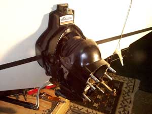
 The rest was relatively easy. I torqued the upper drive
attaching nuts down to spec, rebuilt the water pump, cleaned and painted the
housings, stuck the lower unit back on, and refilled the drive with oil. The
water pump service kit included replacement gaskets for the oil fill plugs, so I
used those. A few days later, I found a few drops of drive oil on the bottom of
my skeg and traced it to the lower fill plug. I put the old plug gaskets back on
in place of the ones from the kit and it hasn't leaked since. The new gaskets
are very hard and apparently don't conform to the mating surfaces as well as the
old ones.
The rest was relatively easy. I torqued the upper drive
attaching nuts down to spec, rebuilt the water pump, cleaned and painted the
housings, stuck the lower unit back on, and refilled the drive with oil. The
water pump service kit included replacement gaskets for the oil fill plugs, so I
used those. A few days later, I found a few drops of drive oil on the bottom of
my skeg and traced it to the lower fill plug. I put the old plug gaskets back on
in place of the ones from the kit and it hasn't leaked since. The new gaskets
are very hard and apparently don't conform to the mating surfaces as well as the
old ones.
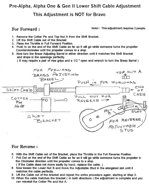
I adjusted the trim limit switch and position sender according
to the manual and adjusted the shift cable according to mercstuff's
procedure. I won't know for certain that I got it right until I get the boat
in the water and begin using it, but the shift cable adjustment didn't seem
anywhere near the rocket surgery that a lot of people make it out to be. There
are two adjustments: the threaded barrel on the cable housing adjusts the
position of the cable along its throw and moving the stud along the slot in the
lever adjusts the total length of the throw. It's just a matter of getting one
end of the throw to stop with the drive fully engaged in forward gear and
getting the other end of the throw to stop with it fully engaged in reverse.
Next - A new cover
Index
